
Highlights
Specifications
| Part Number | ATE9461 |
| Role | RX Receiver |
| HDMI Direction | Output |
| Max Resolution | 3840×2160 @ 60Hz |
| Max Frame Rate | 1080p @ 240Hz |
| Link Rate | VHT40 (802.11ac) |
| Link Encryption | End-to-end encrypted (video, audio, KVM data) with a key created at pairing |
| Wired Ethernet | 100M Ethernet PHY on module; differential pairs on the edge connector, add magnetics and RJ45 on the carrier board |
| Package | 80-pin edge connector |
| Dimensions | 22 × 45 mm |
| Supply | VBUS 3.7 ~ 5.1 V |
| Current | 500 ~ 600 mA |
| Audio Out | DAC L/R |
| Connector ID | ATE9461-S |
| Pairs With | ATE9460 |
Overview
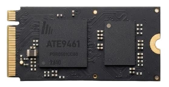
ATE9461 is the 4K60 wireless video receiver that pairs with ATE9460. It takes the stream from 5 GHz or from the built-in 100 Mbps Ethernet port, decodes it and drives a display, projector or recorder through the HDMI connector on the carrier, up to 3840 × 2160 @ 60Hz or 240Hz at 1080p.
At power-up it reads the display EDID and sends it to the transmitter. A built-in audio DAC puts left and right channels on the edge connector, so a headphone jack on the carrier gives analog audio, switching over automatically when headphones go in. When pairing succeeds an OSD appears on the HDMI output with pairing and key information, so installers can confirm the link without a laptop.
The whole video link is encrypted. TX and RX create their own key at pairing, and video, audio and keyboard/mouse data are encrypted all the way. Devices that are not paired cannot join or decode the picture, which suits meeting rooms, hospitals and factories that do not want video leaking out.
USB keyboards, mice, touch screens and barcode scanners on the receiver go back to the host over the reverse channel and appear as local USB devices. The receiver drives HDMI directly, so loop-out does not apply here.
Typical Applications
Signal Chain
Video goes from transmitter to receiver; EDID and keyboard/mouse data travel back to the host. Wireless and wired links use the same pair of modules.
- SourceHDMI
- ATE9460 · Transmitter
- 5 GHz wireless, or Ethernet / fiber
- ATE9461 · Receiver
- Display + keyboardHDMI · USB
4K30 or 4K60
The two series differ in resolution and in how the transmitter provides loop-out.
Apart from resolution and loop-out, the two series share the same size, wireless and Ethernet, link encryption, EDID and KVM behaviour. Their pinouts differ, though, so carriers are not interchangeable and the series do not cross-pair. Loop-out only concerns the transmitter; receivers drive HDMI directly.
ATE9461 Detailed Specifications
Video & Audio
| HDMI direction | Output (module to display) through the HDMI connector on the carrier |
|---|---|
| Interface | HDMI 2.0b (TMDS) |
| Max resolution | 3840 × 2160 @ 60Hz, 4:4:4 / 8-bit (TMDS 594 MHz) |
| High frame rate | 1080p @ 240 / 165 / 144 / 120Hz |
| Other timings | 3840×2160@30/25/24, 2560×1440@60, 1920×1080@60/50/30, 1600×1200@60, 1280×720@60/50, 720×576@50, 720×480@60 |
| Color space | RGB 4:4:4, YCbCr 4:4:4 / 4:2:2 / 4:2:0, auto-detected |
| Color depth | 8-bit / 10-bit (10-bit up to 4K30) |
| HDR | HDR10 static metadata and HLG passed through |
| HDMI audio | LPCM 2.0 / 5.1 / 7.1 passed through; Dolby Digital and DTS bitstreams passed through |
| Decoding | Low-latency H.265 decoding with frame sync |
| Analog audio | Built-in DAC, DAC_L / DAC_R (pins 68 / 70); either this or HDMI audio, switches when headphones are plugged in |
| I²S audio | MCLK / SDO_DACEN / LRCK / SCK / SDI on the edge connector |
| OSD | Pairing and key info overlaid on the HDMI output after pairing |
| End-to-end latency | About 100 ms at 4K60; about 33 ms at 1080p 240 / 120Hz |
EDID & HDCP
| EDID | Reads the display EDID and sends it back to the transmitter; re-reads on power-up, hot-plug or EDID change |
|---|---|
| HDCP | HDCP 2.3 / 1.4, falls back to 1.4 when the display only supports 1.4; the end-product maker needs its own HDCP license |
| Hot-plug | HPD state synced in real time |
Wireless Link
| Band | 5.15 – 5.85 GHz, channels limited by sales region |
|---|---|
| Link rate | VHT40 (802.11ac, 40 MHz) |
| Encryption | Encrypted end to end, covering video, audio and KVM data; key created at pairing; applies to both wired and wireless links |
| Modulation | OFDM, BPSK to 256-QAM, adaptive |
| Range options | AIC8800-D40: 30-100 m; AIC8800-D80: 100-300 m; RTL8812CU: 300-1000 m (line-of-sight figures) |
| Antennas | D40 / D80: one antenna (1T1R); 8812CU: two antennas (2T2R); 4T4R on request |
| Channel selection | Scans and picks the best channel at power-up, can switch while running |
| One-to-many | One TX can broadcast to several RX units |
Wired Link
| Ethernet | Built-in 100 Mbps Ethernet PHY; ETXP / ETXN / ERXP / ERXN on pins 28 / 30 / 32 / 34 |
|---|---|
| Carrier needs | Magnetics + RJ45 |
| Distance | About 500 m through switches or routers; 10 km and 20 km+ with fiber converters |
| KVM | KVM data runs over both the wired and the wireless link |
Power & Electrical
| Supply | VBUS 3.7-5.1 V, typ. 5.0 V; above 5.1 V damages the module |
|---|---|
| Operating current | 500-600 mA (4K60 streaming) |
| Power | 2.3-2.8 W (VBUS 5.0 V) |
| Logic levels | I²C (pin 10 SCL / 12 SDA) 3.3 V LVCMOS, up to 400 kHz |
| Ripple | ≤ 50 mVpp (10 Hz – 20 MHz) |
| VBUS pins | Pins 18 / 20 / 22 / 24, all connected together |
| TMDS | 100 Ω differential, HDMI 2.0b electrical |
Pairing & Control
| Pairing | Shipped pre-paired and links at power-up; hold KEY 5 s to re-pair on site |
|---|---|
| Key & LED | KEY (pin 3) to ground through a button, active low; LED (pin 4) through 2.2 kΩ |
| Spare IO | Pins 15 / 17 / 19; leave open if unused |
Mechanical
| Package | 80-pin edge connector, 0.5 mm pitch |
|---|---|
| Size | 22.0 × 45.0 mm, ±0.15 mm |
| PCB thickness | 0.80 ± 0.07 mm |
| Component height | Top side up to 1.1 mm, bottom side up to 2.1 mm |
| Mounting | M2 screw hole at the far end (2.2 mm) |
| Connector marking | ATE9461-S |
| Paired with | ATE9460 |
Environment & Compliance
| Operating temp. | −20 to +70 °C (ambient at module surface) |
|---|---|
| Storage temp. | −40 to +85 °C |
| Humidity | 10% to 90% RH, non-condensing |
| ESD | ±8 kV contact, ±15 kV air (IEC 61000-4-2) |
| Vibration / shock | 10-500 Hz 1.5 Grms (IEC 60068-2-6); 50 G 11 ms (IEC 60068-2-27) |
| MTBF | ≥ 60,000 h @ 25 °C (Telcordia SR-332) |
| Certification | SRRC, FCC / ISED, CE RED, TELEC, KC; regulatory settings are flashed per sales region, so state the region when ordering; RoHS / REACH |
| Assembly | Plug-in module, do not reflow; MSL 3 moisture-barrier packing |
Dimensions
Carrier Board Design Notes
- Keep VBUS between 3.7 and 5.1 V with at least 1 A per module. Tie pins 18 / 20 / 22 / 24 together and place 22 μF + 100 nF at the edge connector.
- Route the four TMDS output pairs at 100 Ω differential, intra-pair skew under 5 mil and inter-pair under 20 mil, with no layer changes or split crossings.
- For analog audio, wire DAC_L / DAC_R (pins 68 / 70) to a headphone jack. The module switches from HDMI audio to analog when headphones go in.
- Put the pairing button between pin 3 and ground (active low) and the status LED on pin 4 through 2.2 kΩ. Use I²C on pins 10 / 12 if a host MCU needs status.
- For a wired link, connect ETXP / ETXN / ERXP / ERXN (pins 28 / 30 / 32 / 34) to magnetics and an RJ45.
- Leave room for two antennas if you plan on RTL8812CU.
- ATE9461 and ATE9460 have different pinouts, so the RX carrier is its own design, and it cannot be shared with the 4K30 ATE9430T / ATE9430R.
- Leave N and NC pins open. The module runs warm, so leave airflow or a thermal pad over it.
FAQ
Q1Does the ATE9461 4K60 receiver output 1080p at 240Hz?
Q2Does ATE9461 have HDMI loop-out? How do I drive several screens?
Q3How does ATE9461 output audio? Is analog audio supported?
Q4Is the link encrypted? Can the video be intercepted?
Q5How much current does ATE9461 draw and how should the carrier supply be sized?
Q6Where do keyboard and mouse connect in a wireless KVM?
Q7Can you build wireless display receivers or meeting-room receivers OEM / PCBA with ATE9461?
Pairing & Indication
| Action | LED | Result |
|---|---|---|
| Hold KEY 5s | Fast blink | Enters pairing mode and searches for the peer |
| Paired | Solid on | Link up and streaming; the RX overlays an OSD with pairing and key info |
| Hold KEY 25s+ | Slow blink | Factory reset: clears SSID, key and pairing — re-pairing required |
Get the Full Datasheet
Includes the 80-pin assignment, electrical parameters, mechanical drawings and carrier-board guidelines.
Contact UsPairs With & Related
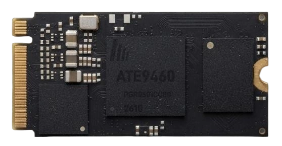
ATE9460 Wireless Video Transmitter
HDMI in, encode, transmit. 80-pin edge connector, 22x45mm, 4K60 with EDID pass-through.
View specs →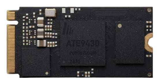
ATE9430T Wireless Video Transmitter with HDMI Loop-out
HDMI in, encode, transmit at up to 4K30. Built-in HDMI loop-out at 4K30 feeds a local monitor without an external splitter.
View specs →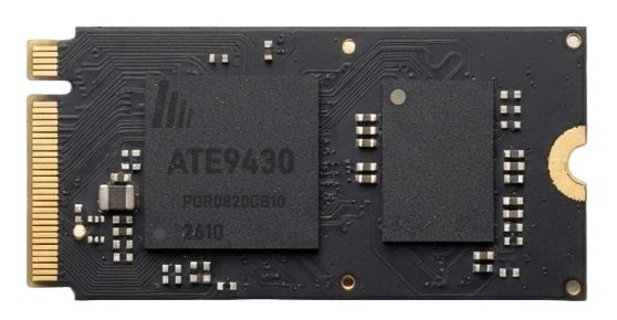
ATE9430R Wireless Video Receiver Module
Receive, decode and output HDMI at up to 4K30, or up to 120Hz at 1080p.
View specs →